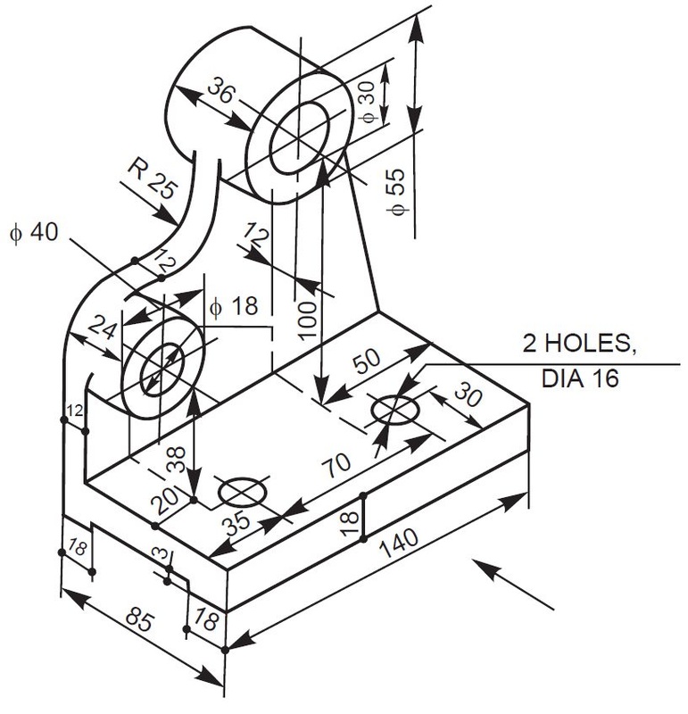
An Engineering Drawing Shows The
An Engineering Drawing Shows The - The boundary between the flat front face of the tab on the left side of the part and the rounded face is called a “tangent edge.” 1.2 historical background and evolution. Web every phase of engineering design starting from concept illustration all the way to the manufacturing phase. It is more than simply a drawing, it is a graphical language that communicates ideas and information. An engineering (or technical) drawing is a graphical representation of a part, assembly, system, or structure and it can be produced using freehand, mechanical tools, or computer methods. Various symbols and abbreviations in engineering drawings give you information about the dimensions, design, and materials used. Web drawing more than one face of an object by rotating the object relative to your line of sight helps in understanding the 3d form. Basically, this type of drawing aims at clearly capturing all the geometric features of products and. Web an engineering drawing is a subcategory of technical drawings. Various symbols and abbreviations in engineering drawings give you information about the dimensions, design, and materials used.
If the isometric drawing can show all details and all dimensions on one drawing, it is ideal. Web an engineering drawing (also named as mechanical drawing, manufacturing blueprints, drawings, dimensional prints, and more) refers to one of the technical drawings, which helps to define engineering products’ requirements. The boundary between the flat front face of the tab on the left side of the part and the rounded face is called a “tangent edge.” Web an engineering drawing is a subcategory of technical drawings. Web any engineering drawing should show everything: The purpose is to convey all the information necessary for manufacturing a product or a part. Web in introduction to engineering drawings, we showed you the building blocks of engineering drawing.
Methods of making engineering drawing. The diagrams also show components that. Engineering drawings use standardised language and symbols. The purpose is to convey all the information necessary for manufacturing a product or a part. The different types of holes used in machining.
Web structural drawings are a series of pages which explain and illustrate the structural design intent of a building or structure. Web in introduction to engineering drawings, we showed you the building blocks of engineering drawing. A bill of materials (bom). According to iso 29845:2011, drawing is “technical information, given on an information carrier, graphically presented in accordance with agreed rules and usually to scale.” An engineering (or technical) drawing is a graphical representation of a part, assembly, system, or structure and it can be produced using freehand, mechanical tools, or computer methods. A complete understanding of the object should be possible from the drawing.
How each type of hole is used in engineering. The boundary between the flat front face of the tab on the left side of the part and the rounded face is called a “tangent edge.” The aim of a good set of structural drawings is to provide the reader with enough information to: Web engineering drawings (aka blueprints, prints, drawings, mechanical drawings) are a rich and specific outline that shows all the information and requirements needed to manufacture an item or product. The example above shows several examples of line style.
Web engineering drawings, also known as mechanical drawings, manufacturing blueprints, drawings, etc., are technical drawings that show the shape, structure, dimensions, tolerances, accuracy, and other requirements of a part in the form of a plan. If the isometric drawing can show all details and all dimensions on one drawing, it is ideal. Web in this way, an engineering drawing can actually show more information than a photograph taken in the same orientation. These drawings are essentially the blueprints or plans for manufacturing a wide array of products and structures.
The Example Above Shows Several Examples Of Line Style.
What the difference is between counterbore and countersink holes. Web an engineering drawing (also named as mechanical drawing, manufacturing blueprints, drawings, dimensional prints, and more) refers to one of the technical drawings, which helps to define engineering products’ requirements. A bill of materials (bom). Web an assembly or subassembly drawing showing all the standard and nonstandard parts in a single drawing.
It Is More Than Simply A Drawing, It Is A Graphical Language That Communicates Ideas And Information.
Electrical & electronics engineering drawing. Basically, this type of drawing aims at clearly capturing all the geometric features of products and. The symbols used for each hole and how they are shown on engineering drawings. It is generally used by engineers,.
522K Views 3 Years Ago Orthographic Projections.
The purpose is to convey all the information necessary for manufacturing a product or a part. Web engineering drawing is a specialized form of communication that uses a strict set of symbols, standards, and perspectives to depict mechanical, electrical, or structural designs. Web any engineering drawing should show everything: Web table of contents.
An Engineering (Or Technical) Drawing Is A Graphical Representation Of A Part, Assembly, System, Or Structure And It Can Be Produced Using Freehand, Mechanical Tools, Or Computer Methods.
If the isometric drawing can show all details and all dimensions on one drawing, it is ideal. The boundary between the flat front face of the tab on the left side of the part and the rounded face is called a “tangent edge.” Sometimes using main orthographic views is impossible to show all the features of an object to the degree that the object is sufficiently described for manufacturing. Various symbols and abbreviations in engineering drawings give you information about the dimensions, design, and materials used.


